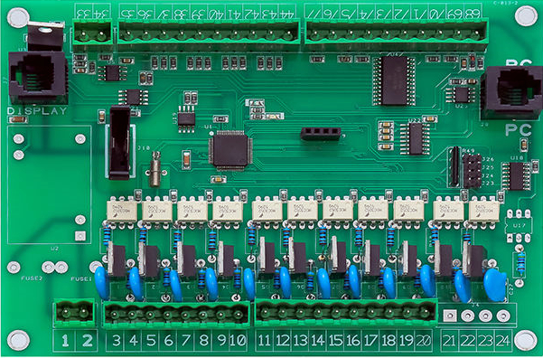
There are many PCB design rules. The following is an example of electrical safety spacing. Electrical rule setting is the design circuit board in the wiring must abide by the rules, including the safety distance, open circuit, short circuit setting. The setting of these parameters will affect the production cost, design difficulty and design accuracy of the designed PCB, and should be treated strictly.
1.Clearance Rules
PCB design has the same network spacing, different network safety spacing, other, line width need to be set, the default line width and spacing are 6mil, the default spacing is 6mil, the minimum line width is set to 6mil, the recommended value (the default wiring width) is set to 10mil, the maximum is set to 200mil. Specific Settings according to the difficulty of the board wiring setting.
The set line width and spacing also need to be negotiated with the PCB manufacturer in advance, because some manufacturers may not be able to achieve the set line width and spacing due to the problem of process capacity, and the smaller the line width and spacing, the higher the cost.
2.Line spacing 3W rule
All are designed in clock line, differential line, video, audio, reset line and other system critical lines. When multiple high-speed signal wires travel long distances, in order to reduce cross-talk between lines, the line spacing should be large enough. When the line center spacing is not less than 3 times the line width, most electric fields can not interfere with each other, which is the 3W rule. The 3W rule keeps 70% of the fields from interfering with each other, and with 10W spacing, 98% of the fields can be achieved without interfering with each other.
3.20H rule for the power layer
The 20H rule refers to the 20H distance between the power supply layer and the formation, which is of course to inhibit the edge radiation effect. Because the electric field between the power layer and the ground is changing, electromagnetic interference will radiate outward at the edge of the plate, which is called edge effect. The solution is to shrink the power supply layer so that the electric field is only transmitted within the range of the ground. With one H(the thickness of the medium between the power source and the ground) as the unit, 70% of the electric field can be confined to the edge of the ground with a contraction of 20H, and 98% of the electric field can be confined with a contraction of 100H.
4.Influence of impedance line spacing
A complex structure of impedance control consisting of two differential signal lines. The input signals at the driver end are two signal waveforms of opposite polarity, respectively transmitted by two differential lines, and the two differential signals at the receiver end are subtracted. This method is mainly used in high-speed digital analog circuits for better signal integrity and noise resistance. The impedance is proportional to the difference line spacing, and the greater the difference line spacing, the greater the impedance.
5.Electrical creepage distance
Electrical clearance and creepage distance are more important in PCB design of high voltage switching power supply. If the electrical clearance and creepage distance are too small, it is necessary to pay attention to the leakage situation. Creepage spacing and electrical gap During PCB design, the electrical gap can be adjusted by layout to adjust the spacing from the pad to the pad. When PCB space is tight, creepage spacing can be increased by grooving.


